The Boy Electrian: Chapter 17 - Dynamos
"The boy electrian" is a book written by Alfred P. Morgan, describing practical electrical projects one could do at home at the time the book was written in 1913. Since the only versions of this book available on the internet are of somewhat ordinary quality scans, I've decided to transcribe one of the chapters into digital text, by hand. Why you ask? Well I asked myself that as well, however I've already transcribed about four pages by that time so it didn't seem to be a good idea to quit half-way through.
Below you will see chapter 17 of the book where the author describes the function as well as how to construct a dynamo (a electrical generator that creates direct current) from both spare parts and from more professional quality materials. I've transcribed this based on the July 1914 version of the book, altering only some punctuation marks and altering the spelling of two words (to-day, back yard) to counterparts much more familar to the modern reader. I've also straighten and altered the colours of the images to something more readable. I hope my impulsive decision to transcribe this brings some convenience to anyone interested in the construction of a dynamo!
Chapter XVII - Dynamos
There is perhaps no other electrical device entering into the young experimenter’s domain requiring the careful workmanship and tool facilities that the dynamo does. In order to construct a practical working dynamo it would be necessary to have at hand a lathe for turning the castings.
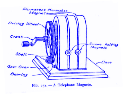
Rather than describe a machine which comparatively few of my readers would be able to build, I have explained below how it is possible to so alter an old telephone magneto that it may be made to serve as a small dynamo. Telephone magnetos, also sometimes called hand generators, are used in many telephone systems to supply the current which rings the telephone bell at the other end. The magneto is placed in a small box on the telephone, only the handle being exposed. In order to make a call the handle is given several brisk turns before raising the receiver. When the handle is turned the moving parts of the generator revolve and produce a current of electricity which goes forth over the line and rings the bell at the other end.
Telephone magnetos are gradually being discarded in all the large telephone systems, a method known as “central energy”, in which the current for ringing bells is supplied from the central office, taking their place. For that reason, there are a great many telephone magnetos to be found in second-hand shops and at electrical houses, where they can be purchased for a fractional part of the original cost. Fifty cents will buy a first-class second-hand telephone magneto.
The author saw a pile of telephones as large as a haystack, each telephone containing a magneto, in the backyard of a second-hand shop, and the owner would have been glad to sell the complete instruments for fifty cents each.
Before explaining how to reconstruct such a machine, it is best to impress upon the reader that a careful study of the principles of the dynamo is well worth the time spent. Almost any book on physics or electricity, or even the encyclopaedia, will be found to contain a description of this wonderful machine that supplies the power for running the trolley cars, electric lights, etc., in fact all of the electricity in use today with the exception of that generated by batteries for telegraph and telephone lines.
It will be remembered that if a bar magnet is suddenly plunged into a hollow coil of wire; a momentary electric current will be generated in the coil. The current is easily detected by means of an instrument called a galvanometer. The space in the vicinity of a magnet is filled with a peculiar invisible force called magnetism. The magnetism flows along a certain path, passing through the magnet itself and then spreading out in curved lines. If a sheet of paper is laid over a magnet and a few iron filings are sprinkled on the paper, they will follow the magnetic lines of force.
When the magnet is plunged into the hollow coil, the lines of force flow through the turns of wire, or are said to cut them. Whenever lines of force cut a coil of wire and they are in motion, electricity is produced. I t does not matter whether the coil is slipped over the magnet or the magnet is plunged into the coil, a current will be produced as long as they are in motion. As soon as the magnet or the coil stops moving, the current stops.
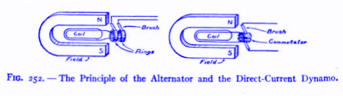
By arranging a coil of wire between the poles of a horse-shoe magnet so that it can be made to revolve, the motion can be made continuous and the current of electricity maintained.
Figure 252 shows such an arrangement. Some means of connection with the coil of wire must be established so that the current can be led off. If two metal rings are connected to the ends of the coil, connection can be made by little strips of metal called brushes rubbing against the rings. This scheme is the principle of the telephone magneto and the basis of all dynamos.
In the telephone magneto, more than one horseshoe magnet is usually provided. The coil of wire revolves between the poles of the magnets. The coil is wound around an iron frame and together they are called the armature.
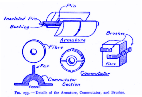
The end of the armature shaft is fitted with a small spur gear meshing with a larger gear bearing a crank, so that when the crank is turned the motion is multiplied and the armature is caused to revolve rapidly. One end of the coil or armature winding is connected to a small brass pin. This pin connects with a second pin set in the end of the shaft in an insulating brush of hard rubber. The other terminal of the coil is connected to the armature itself. Thus connection can be had to the coil by connecting a wire to the frame of the machine and to the insulated pin.
The armature of a magneto is usually wound with a very fine silk insulated wire, about No. 36 B & S. gauge in size. This should be carefully removed and wound upon a spool for fut9ure use. Replace the wire with some ordinary cotton-covered magnet wire, about No. 24 or 25 B. & S. gauge, winding it on very carefully and smoothly. Connect one end of the winding to the pin leading to the insulated pin by soldering it. This pin is the one at the end of the shaft opposite to that one to which the spur gear is fastened. Connect the other end of the wire to the pin at the same end of the shaft as the gear. This pin is grounded, that is, connected to the frame.
An ordinary telephone magneto gives a very high voltage current. The voltage may vary from twenty-five to several hundred, depending upon how fast the machine is run. This is due to the fact that the armature winding is composed of a very large number of turns of wire. The more turns that are placed on the armature, the higher its voltage will be. The current or amperage of a large telephone magneto wound with a large number of turns of fine wire is very low. Too low in fact to be used for anything except ringing a bell or testing. Winding the armature with fewer turns of large wire reduces the voltage and increases the amperage so that the current will light a small lamp or may be used for other purposes. The winding does not change the principle of the magneto, it merely changes its amperage and voltage.
The magneto may be mounted on a wooden base-board and screwed to a table, so that the handle may be turned without inconvenience. A small strip of copper, called a brush, should be fastened to the base with a screw and brought to bear against the end of the insulated pin. The brush should be connected to a binding-post with a piece of wire. A second wire leading to a binding-post should be connected to the frame of the magneto. When the handle is turned rapidly, currents may be drawn from the two binding-posts. The current is of the kind known as alternating, that is to say, it flows first in one direction, then reverses and flows in the other.
In order to make the machine give direct current, it must be fitted with a commutator. This is somewhat difficult with some magnetos but the following plan may be carried out in most cases. Cut a small fiber circle or disk about one inch in diameter from sheet fiber three-sixteenths of an inch thick. Cut a small hole in the center, just large enough so that the fiber will slip very lightly over the end of the shaft from which the insulated pin projects. Two small commutator sections similar to that shown in Figure 253 must be cut from sheet-brass or sheet-copper. The three long ears shown in the drawing are bent back around the fiber and squeezed down flat with a pair of pincers so that they grip the fiver very tightly and will not slip. One ear on one section should be bent over the back down to the hole, where it will connect with the shaft. The other section of the commutator is connected to the insulated pin by a drop of solder. In this manner, one end of the winding is connected to one section of the commutator and the other end to the other section. The commutator should fit tightly on the end of the shaft so that it will not twist. The dividing line between the section should be parallel to a line drawn to the axis of the actual armature coil. When the iron parts of the armature are nearest the poles of the horseshoe magnets in their revolution, the slot in the commutator should be horizontal.
When the magnet is provided with a commutator, it may also be run as a motor by connecting it to a battery. In order to operate it either as a dynamo or a motor, however, it must first be fitted with a pair of brushes. They are shown in detail in Figure 253. They are made from two small strips of sheet-copper bent as shown and mounted on a small wooden block. They must be adjusted to bear against the commutator so that when the dividing line between the two sections is horizontal, the upper brush bears against the upper section and the lower brush against the lower section. The two brushes form the terminals of the machine. They should be connected to binding-posts.
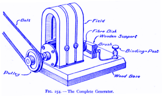
In order to operate the dynamo properly and obtain sufficient current from it to operate a couple of small incandescent lamps, it will have to be provided with a pulley mounted on the end of the shaft after the gear wheel has been removed. The dynamo may then be driven at high speed by connecting it to a sewing-machine with a belt, or the back wheel of a bicycle from which the tire has been removed.
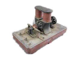
The completed dynamo is shown in Figure 254. The voltage and amperage of the dynamo will depend upon the machine in question, not only upon the size of the wire but also upon the size of the machine, the speed at which it is run, and the strength of the horseshoe magnets. It is impossible to tell just what the current will be until it is tested and tried.
A 10-Watt Dynamo
Probably few experimenters fully understand how almost impossible it is to construct a dynamo, worthy of the name as such, without resort to materials and methods employed in the commercial manufacture of such machines. Practical telegraph instruments, telephones, etc., can be constructed out of all sorts of odds and ends, but in order to make a real dynamo it is necessary to use certain materials for which nothing can be substituted.
- The field magnets must be soft gray cast-iron except in special instances.
- The wire used throughout must be of good quality and must be new.
The necessity for good workmanship in even the smallest detail cannot be overestimated. Poor workmanship always results in inefficient working. No dynamo will give its stated output continuously and safely unless the materials and workmanship are up to a high standard.
Since castings must be used as field magnets, a pattern is necessary to form the mould for the casting. Pattern work is something requiring skill and knowledge usually beyond the average experimenter. A lathe is necessary in order to bore or tunnel the space between the ends of the field magnet into which the armature fits.
It may be possible for several boys to club together and have a pattern made by a pattern-maker for building a dynamo. Then by using the lathe in some convenient shop or manual training school secure a field magnet and armature for a really practical small dynamo.
For these reasons, I have described below a small dynamo of about ten watts output, the castings for which can be purchased from many electrical dealers with all machine work done at an extremely low price.
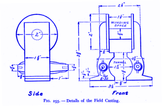
The field magnet shown in Figure 255 is drawn to scale and represents the best proportions for a small “overtype” dynamo of ten to fifteen watts output. The dimensions are so clearly shown by the drawings that further comment in that respect is unnecessary.
The armature is of the type known as the “Siemen’s H.” It is the simplest type of armature it is possible to make, which is a feature of prime importance to the beginner at dynamo construction, although it is not the most efficient form from the electrical standpoint. The armature in this case is also a casting and therefore a pattern is required.
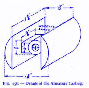
The patterns for both the field and the armature are of the same size and shape as shown in Figures 255 and 256. They are made of wood, and are finished by rubbing with fine sandpaper until perfectly smooth and then given a coat of shellac. The parts are also given a slight “draft,” that is, a taper toward one side, so that the pattern may be withdrawn from the mould.
The patterns are turned over to a foundry where they are carefully packed in a box, called a “flask,” full of moulder’s sand. When the patterns are properly withdrawn, they will leave a perfect impression of themselves behind in the sand. The mould is then closed up and poured full of molten iron. When the iron has cooled the castings are finished except for cleaning and boring.
The shaft is a piece of steel rod, three-sixteenths of an inch in diameter, and four and one-half inches in length. The portion of the field into which the armature fits is bored out to a diameter of one and five-sixteenth inches. Considerable care is necessary in performing this operation in order not to break the field magnet apart by taking too heavy a cut.
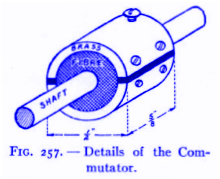
The armature should be turned down to a diameter of one and one-quarter inches or one-sixteenth of an inch smaller than the tunnel in which it revolves between the field magnets. The center of the armature is bored out to fit the shaft. Figure 257 shows a two-part commutator for fitting to an armature of the “Siemen’s H” type. It consists of a short piece of brass tubing fitted on a fiber core and split length-wise on two opposite sides, so that each part is insulated from the other.
The fiber is drilled with a hole to fit tightly on the shaft. It is then placed in a lathe and turned down until a suitable piece of brass tube can be driven on easily. Two lines are then marked along the tube diametrically opposite. A short distance away from each of these lines, and on each side of them, bore two small holes to receive very small wood screws. The screws should be counter-sunk. It is very important that none of the screws should go into the fiber core far enough to touch the shaft.
The commutator may then be split along each of the lines between the screws with a hacksaw. The saw-cut should be continued right through the brass and slightly into the insulating core. The space between the sections of the commutator should be fitted with well-fitting slips of fiber, glued in. The commutator should now be trued up and made perfectly smooth.
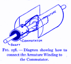
The commutator is provided with a small brass machine screw threaded into each section near the edge as shown in Figure 257. These screws are to receive the ends of the armature winding and so facilitate connections. The commutator, shaft and armature are assembled as shown in Figure 258. The armature may be held to the shaft by a small set screw or a pin. The commutator should fit on the shaft very tightly so that it will not slip or twist.
Every part of the armature and shaft touched by the armature winding must be insulated with paper which has been soaked in shellac until soft. The armature must be left to dry before winding.
The armature should next be wound with No. 20 B. & S. gauge single-cotton-covered magnet wire. Sufficient wire should be put on to fill up the winding space completely. Case should be taken, however, not to put on too much wire or it will interfere with the field magnets and the armature cannot revolve. After winding the armature, test it carefully to see that the wire is thoroughly insulated from the iron. If the insulation is correct, paint the whole armature with thick shellac varnish and bake it in a warm oven to set the shellac.
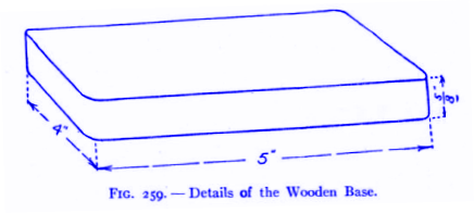
Figure 258 is a diagram showing how the winding is made and connected. It is wound about the armature, always in the same direction, just as if the armature were an ordinary electro-magnet.
The ends of the winding are each connected to one of the commutator sections by scraping the wire and placing it under the screws. The winding space in the field magnet should be shellacked and insulated with brown paper by wrapping the core with a strip of paper and covering the bobbin ends with circular pieces made in two halves. The field magnet is wound full of No. 20 B. & S. gauge single-cotton-covered wire. The wire should be put on in smooth, even layers and the winding space completely filled up.
The base for the dynamo is a piece of hard wood, five inches long, four inches wide, and five-eighths of an inch thick.
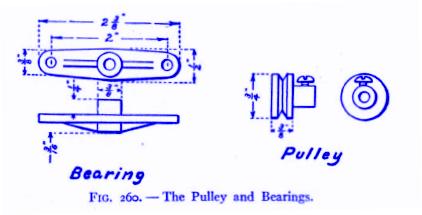
The bearings are small brass castings of the dimensions shown in Figure 260. It is necessary first to make a wooden pattern and send it to the foundry for the castings. The bearings are fastened to the projecting arms on the field casting by means of machine screws eight-thirty-seconds of an inch in thickness.
The field magnet should not be screwed down on to the base until the armature runs easily and truly in the tunnel.
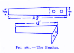
The brushes are made from thin gauge sheet-copper according to the shape and dimensions shown in Figure 261. They are bent at right angles and mounted on the base on either side of the commutator with small round-headed wood screws.
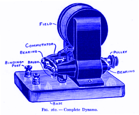
The completed dynamo is shown in Figure 262. One end of the shaft is provided with a small pulley to accommodate a small leather belt.
The dynamo is connected as a “shunt” machine, that is, one terminal of the field magnet is connected to one of the brushes, and the other terminal to the other brush. A wire is then led from each of the brushes to a binding-post. A shunt dynamo will only generate when run in a certain direction. In order to make it generate when run in the opposite direction, it is necessary to reverse the field connections.
The dynamo just described should have an output of from 10 to 15 watts and deliver about 6 volts and 1¾ to 2½ amperes. In order to secure current from the dynamo it will first be necessary to magnetize the field by connecting it to several batteries. It will be found that the dynamo will also operate as a very efficient little motor, but that on account of having a two-pole armature it must be started by giving the shaft a twist. It can be used as a generator for lighting small lamps, electro-plating, etc., but cannot be used for recharging storage cells on account of having a two-pole armature.
The dynamo may be driven with a small water motor or from the driving-wheel of a sewing-machine.
Before the machine will generate as a dynamo, it must be connected to a battery and run as a motor. This will give the field the “residual magnetism” which is necessary before it can produce current itself.